
Understanding Compression Ratio in Injection Screws
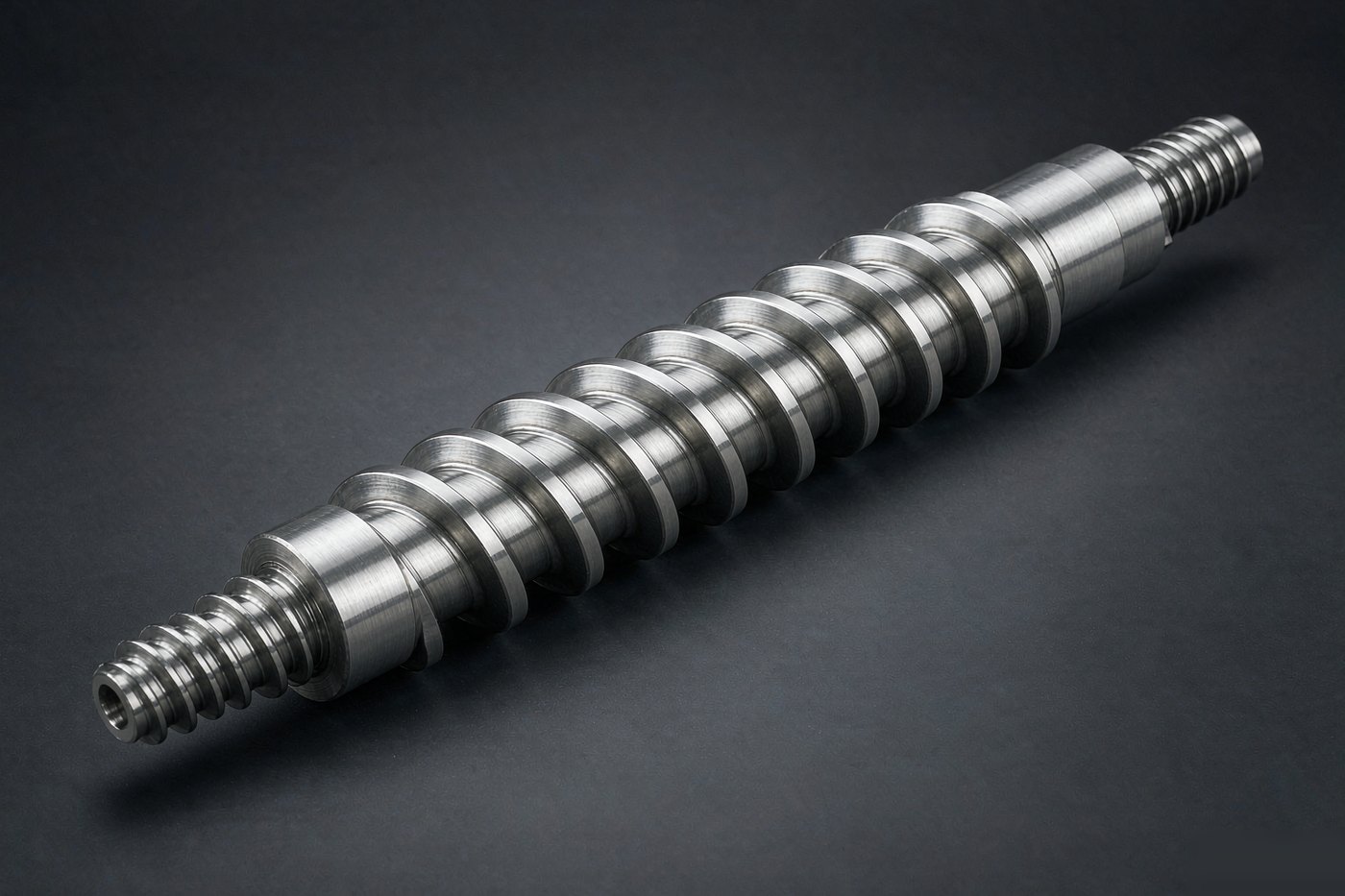
Compression ratio describes how much the screw channel volume shrinks between the feed zone and the metering zone. It is set by the flight depth at each end, and it determines how much the resin is worked on the way down the barrel.
How it is calculated
Ratio = feed zone channel depth / metering zone channel depth, measured perpendicular to the flight. A screw with a 9 mm feed depth and a 3 mm metering depth has a 3:1 ratio. It is a geometric number, not a pressure number — pressure comes from the die and the process, not from the ratio.
Typical values
- 2.0 - 2.5:1 — shear sensitive resins: PVC, some PC grades, flame-retardant compounds
- 2.5 - 3.0:1 — general purpose: PE, PP, PS, ABS
- 3.0 - 3.5:1 — engineering resins: PA, PBT, POM, PC
- Above 3.5:1 — special cases, usually with barrier screws rather than a single flight
Why it matters in practice
Too low a ratio and the resin is not compacted enough: you get unstable feeding, air entrapment and inconsistent melt density. Too high a ratio and the resin is over-sheared: melt temperature climbs, degradation products form, and you get black specks and splay that no amount of purging fixes.
The effect is easy to see in the purge: a screw running too high a ratio often produces a melt that is hotter than the barrel setpoint by 20 - 30 °C at the same screw speed. If you reduce back pressure and screw speed and the temperature normalises, the geometry is working the resin harder than it needs.
Related geometry
Compression ratio is only one of four numbers. The others are L/D ratio (typically 20:1 to 24:1 for injection), flight pitch, and the length of each zone. A screw that is "the same ratio" as another can behave very differently if the compression zone is short and abrupt.
If you are specifying a replacement, send the resin grade and the existing screw drawing; we will check the geometry rather than copy a worn screw that may never have been right for the job. See injection molding screws.
Related products